🚫
Public Alpha. Zeroth-01 Bot is available for basic demos, please expect breaking changes until 1.0 is reached.
⚠️
Documentation may be out of date or incomplete. Always see our Discord for the most up-to-date information.
Assembly Guide
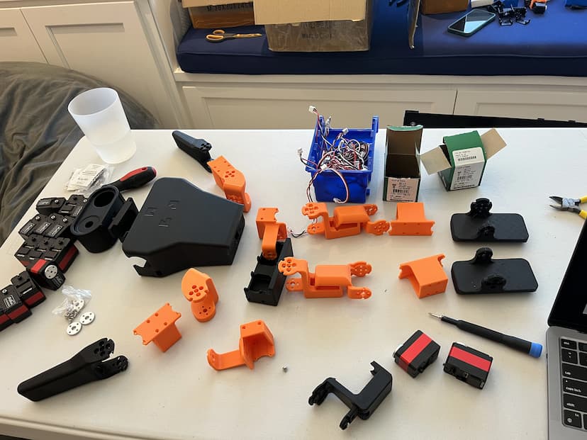
Before assembly, check both the Bill of Materials and 3D printing guide to make sure you have all of the parts.
Show parts list
Notes:
- All screws should have spring washers to prevent loosening, especially on legs and hips.
- Use an M3x8 screw for the middle screw on every servo.
Prepare Components
- Remove all supports and prepare components for assembly.
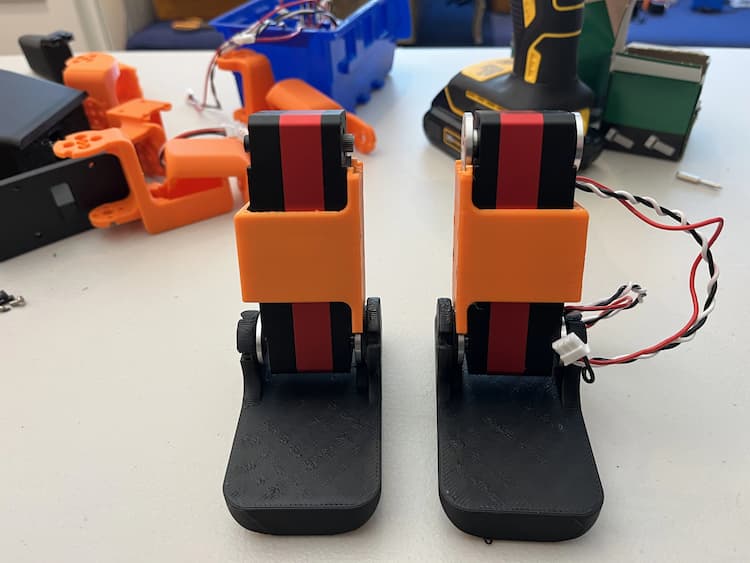
Assemble Ankle Pitch Servos to Feet
- Connect the left and right ankle pitch servos to the feet.
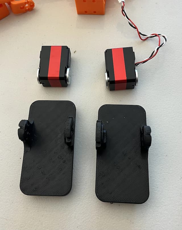
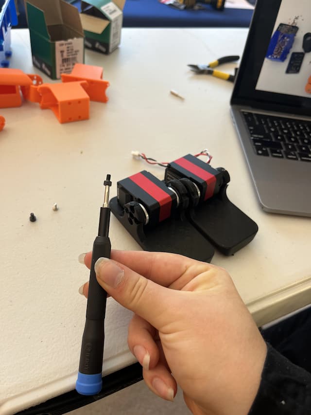
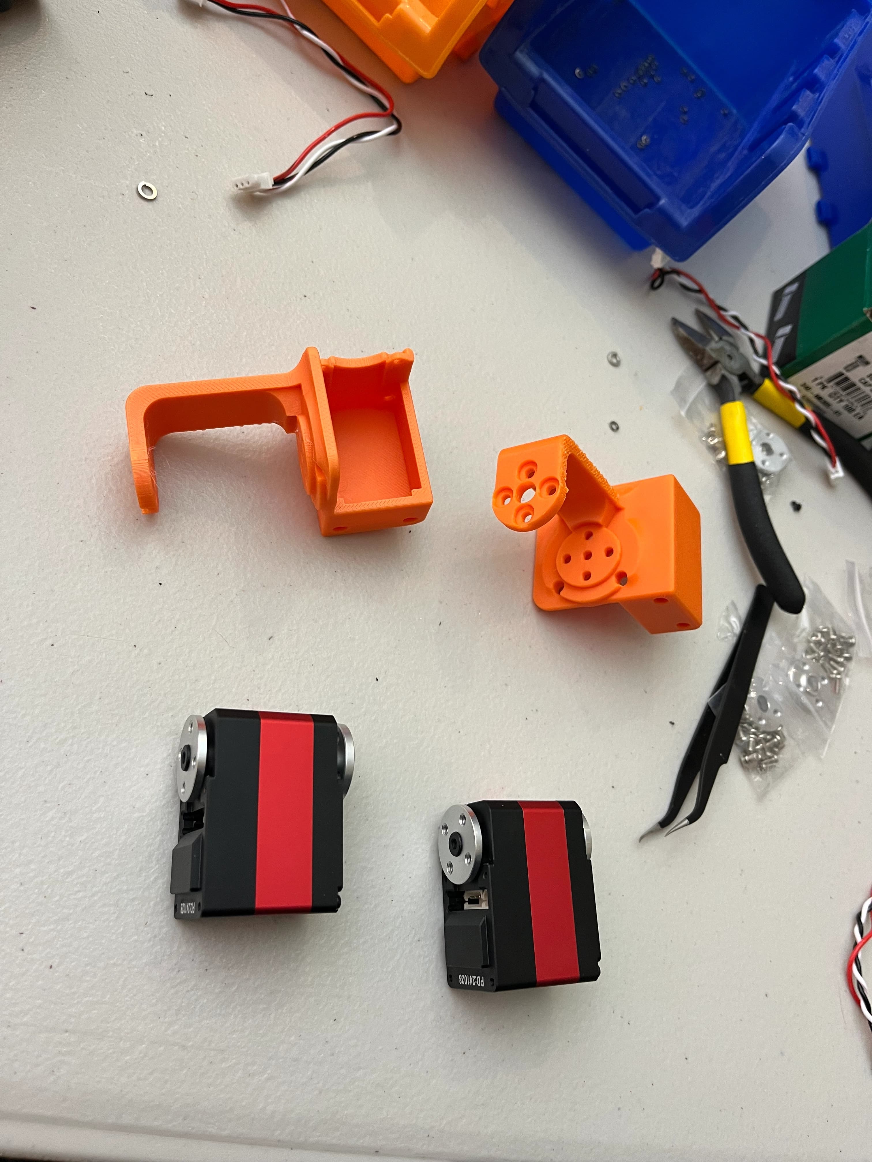
Attach Servo Casings
- Secure the servo casings to the ankle pitch servos.
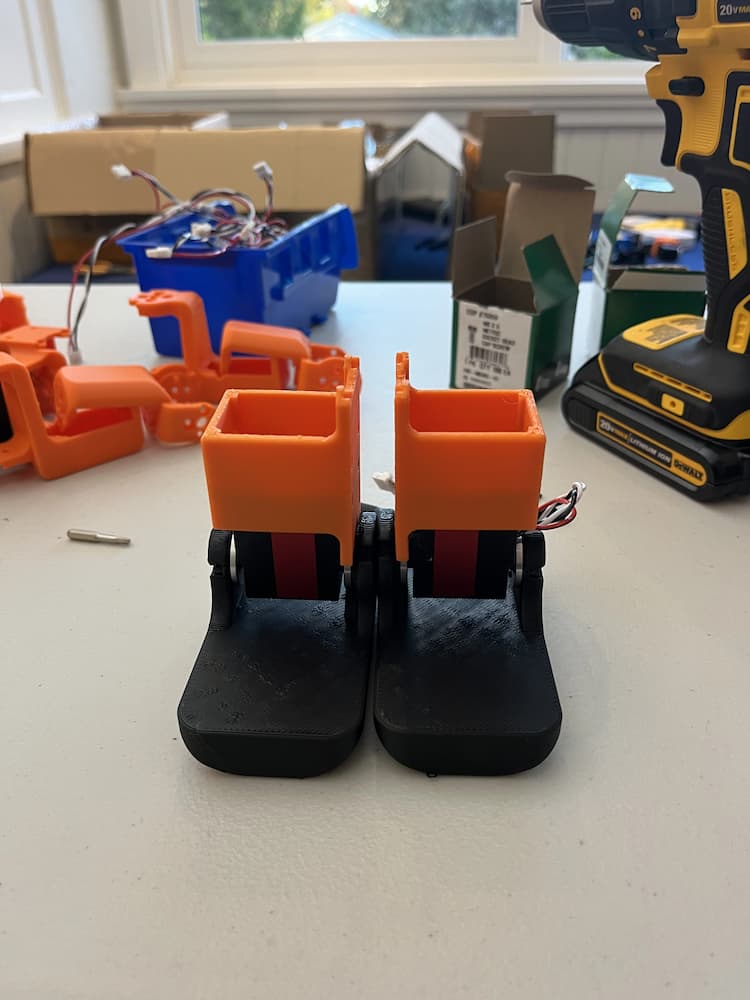
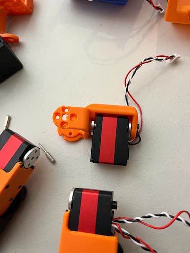
Install Knee Pitch Servos and Wiring
- Attach the right and left knee pitch servos to the assembly.
- Connect the wire from the right foot to the left port of the knee servo.
- Add a new wire to the right port of the knee servo.
- Repeat for the left leg (mirrored configuration).
Assemble Knees and Hip Roll Servos
- Connect knee parts to the right and left knee pitch servos.
- Attach the left and right hip roll servos and the backs of knees/hip yaw connectors.
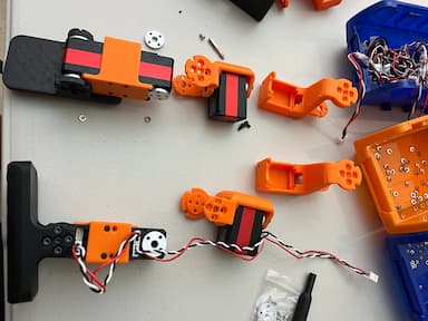
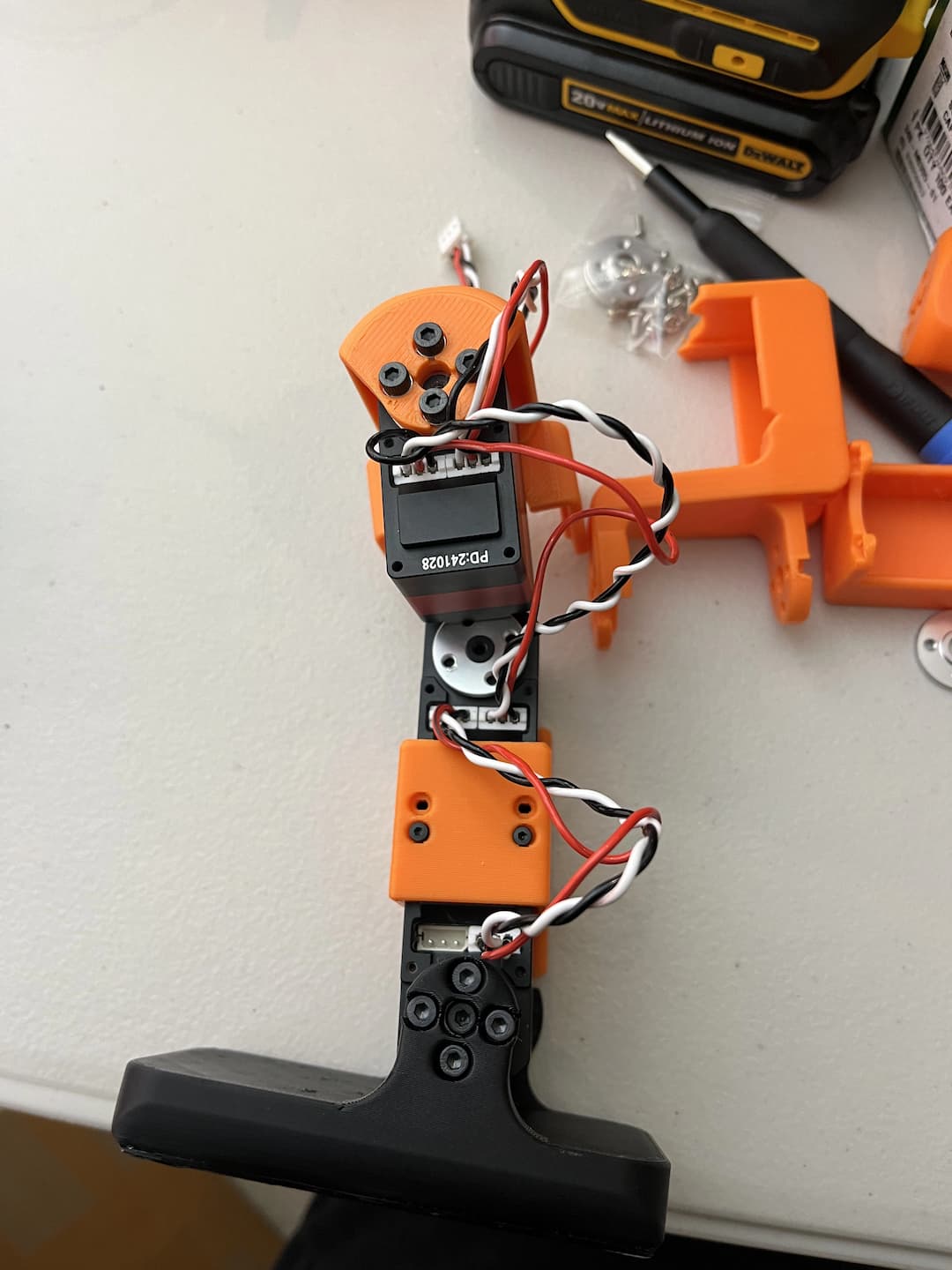
Verify Wiring Configuration
- Ensure the wire configuration on the right leg matches the images below.
- The left leg wiring should be mirrored accordingly.
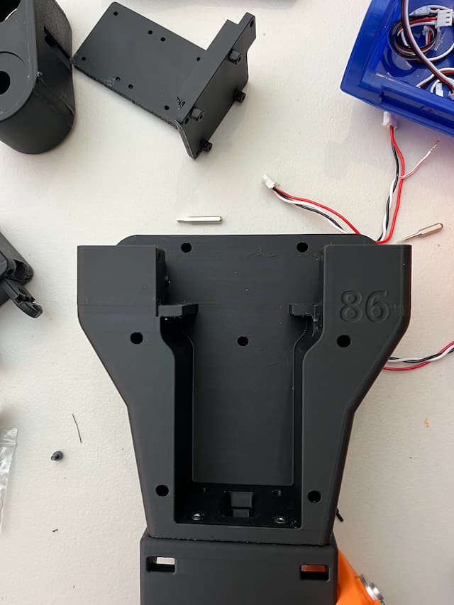
Secure Torso
- Use four M3x12 screws and four nuts to secure the torso as shown.
Attach Hip Yaw Servos to Legs
- Connect the right and left hip yaw servos to the legs and then to the hip connectors.
- Important: Do not attach the torso-connecting servos at this point.
- You should now have two legs with four servos each, not yet connected to the torso.

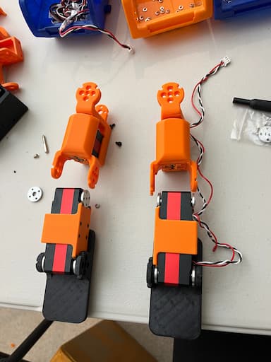
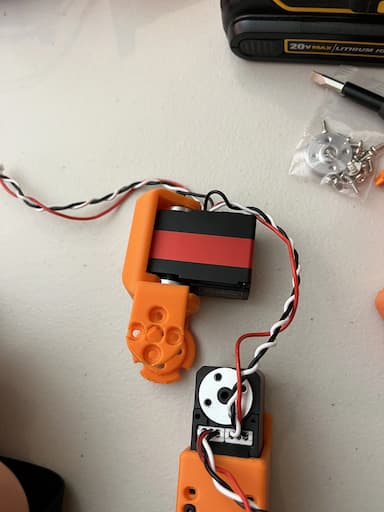
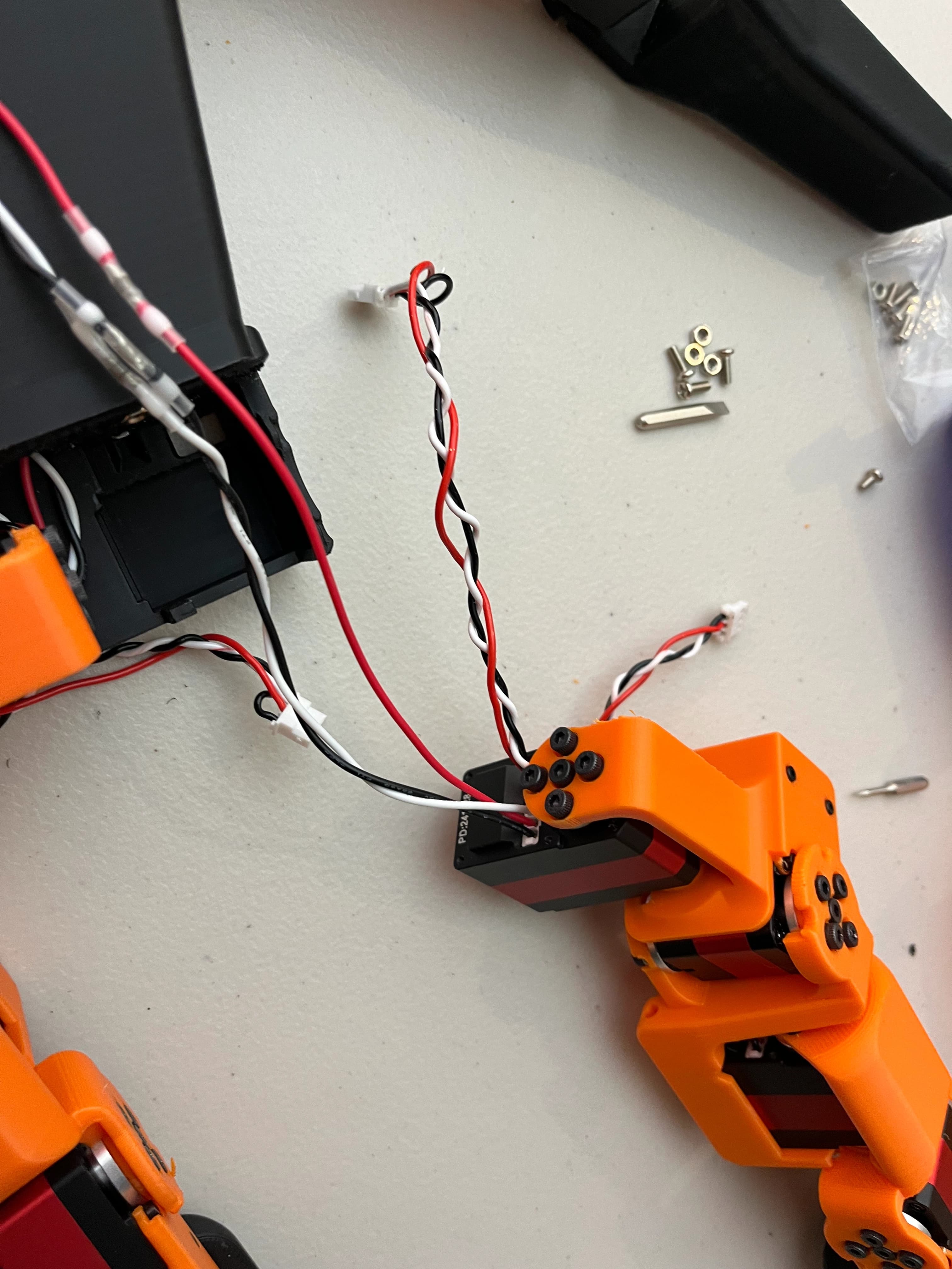
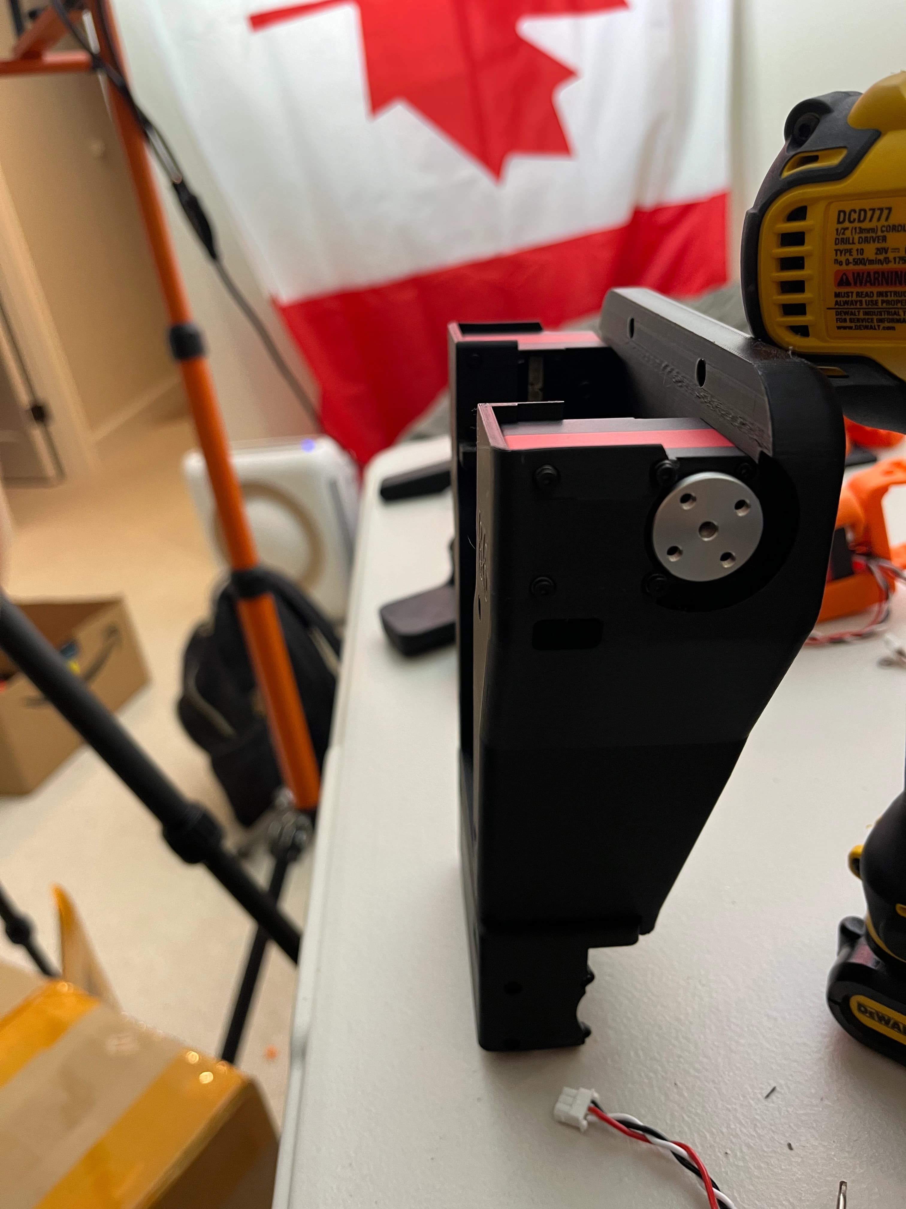
Prepare Hip Pitch Servos Wiring
- Connect a short and a long wire to the hip pitch servo that connects to the torso (red-striped servo).
- Note: In the image below, the wires are plugged into the wrong ports; they should be switched.
- Thread the long wire up towards the head.
- Thread the short wire through the back hole to the top thigh.
- Important: Do not attach the hip pitch servo to the leg yet, as it will prevent securing it to the torso.
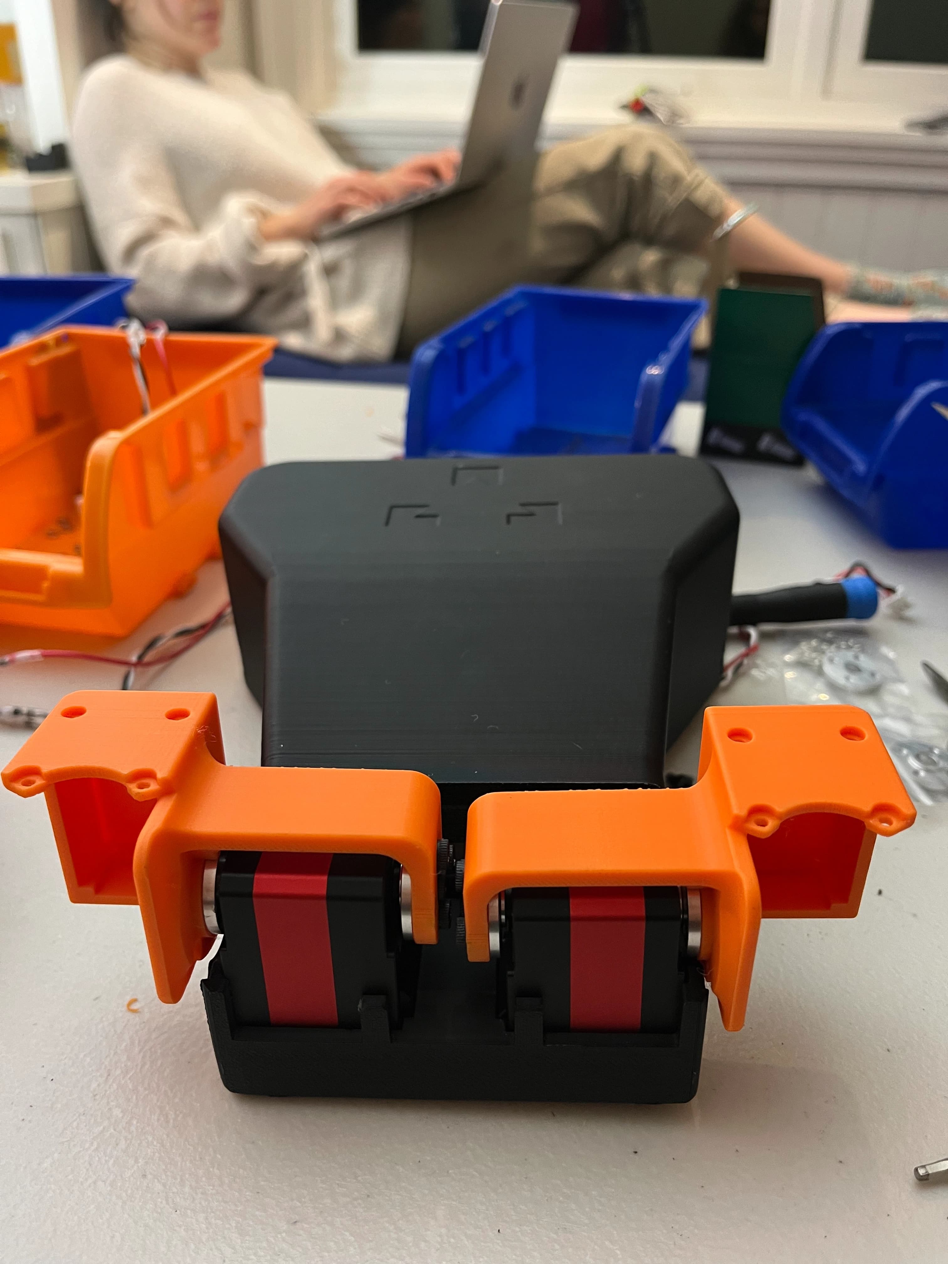
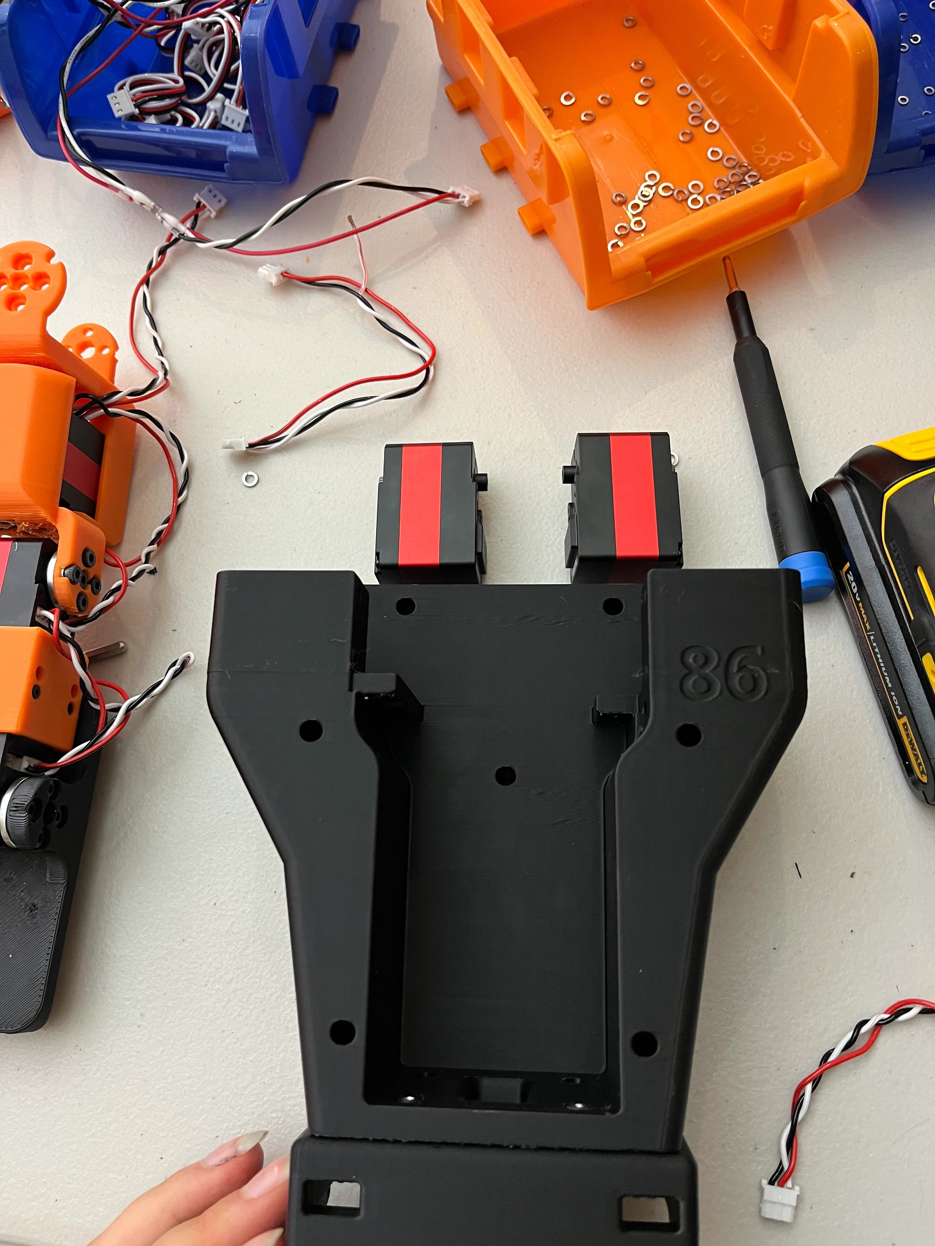
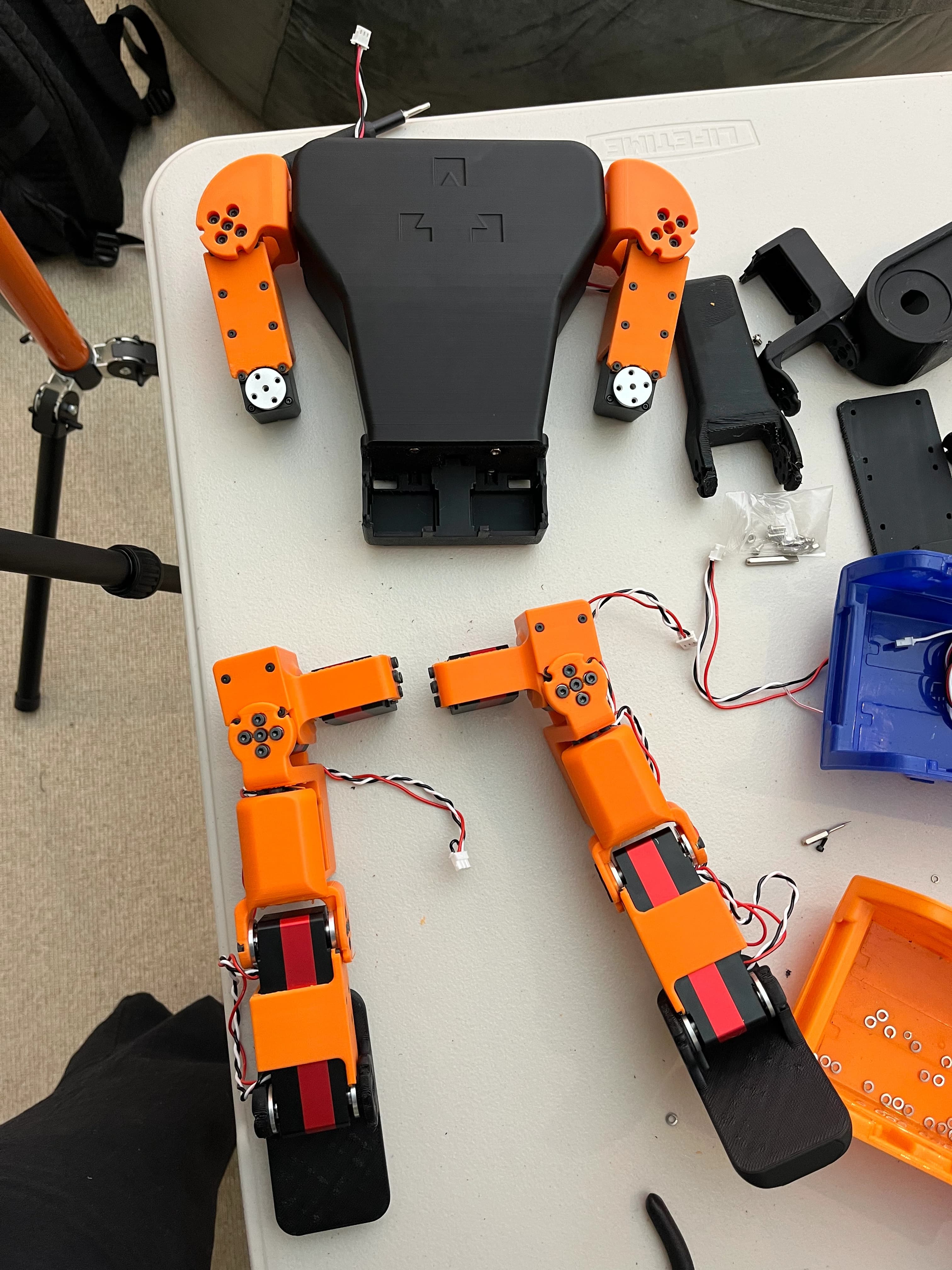
Attach Hip Pitch Servos to Torso
- Secure the right and left hip pitch servos to the torso.
- Note: The orange parts should not be connected to the legs yet.
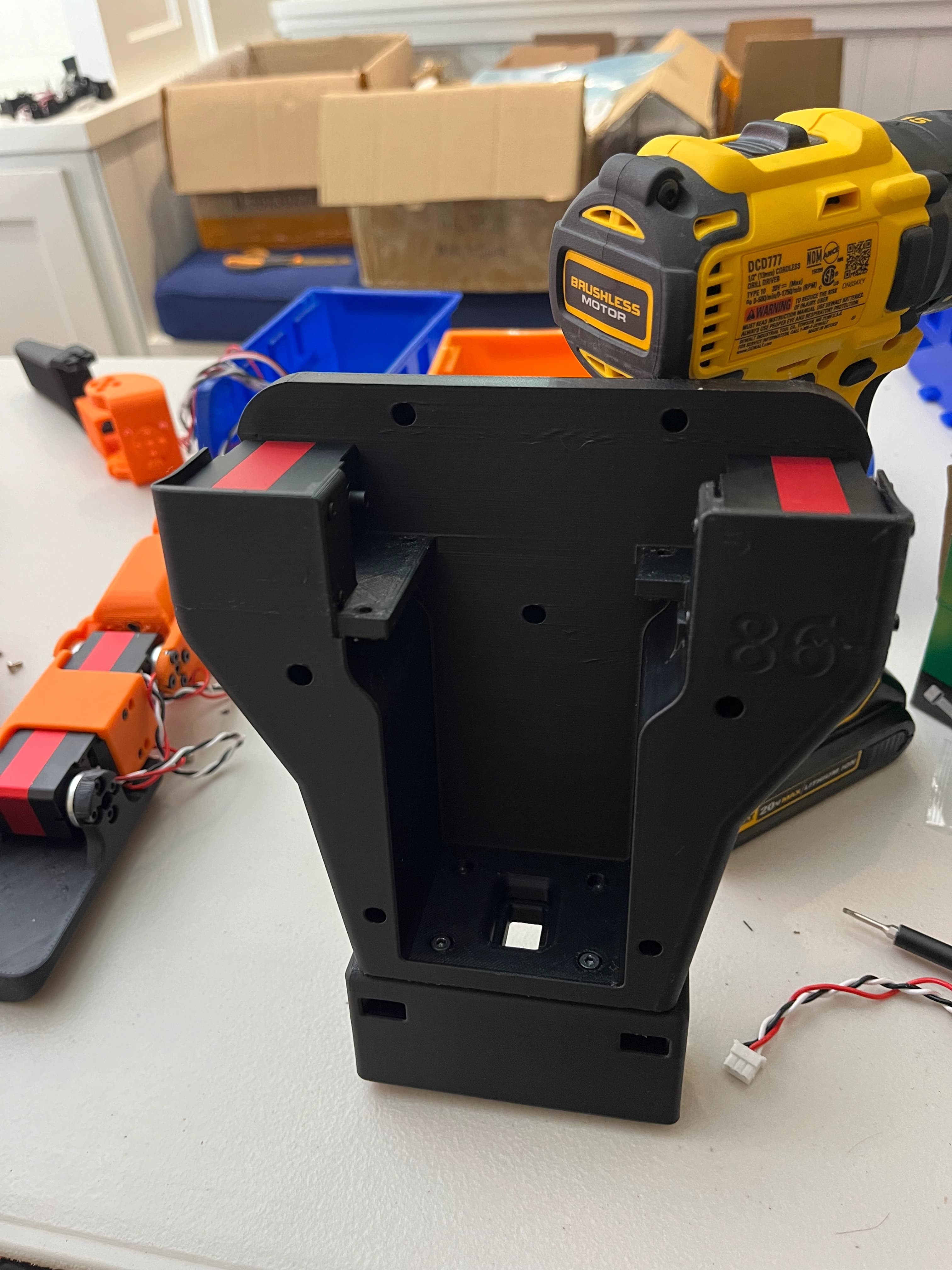
Connect Legs to Hip Pitch Servos
- Attach the assembled legs to the hip pitch servos.
- The legs are now securely connected to the torso.
(Refer to the image from Step 10, now with legs attached.)
Install Shoulder Pitch Servos
- Secure the right and left shoulder pitch servos (black-striped servos) to the torso.
Attach Shoulders to Torso
- Attach the shoulders onto the torso using screws.

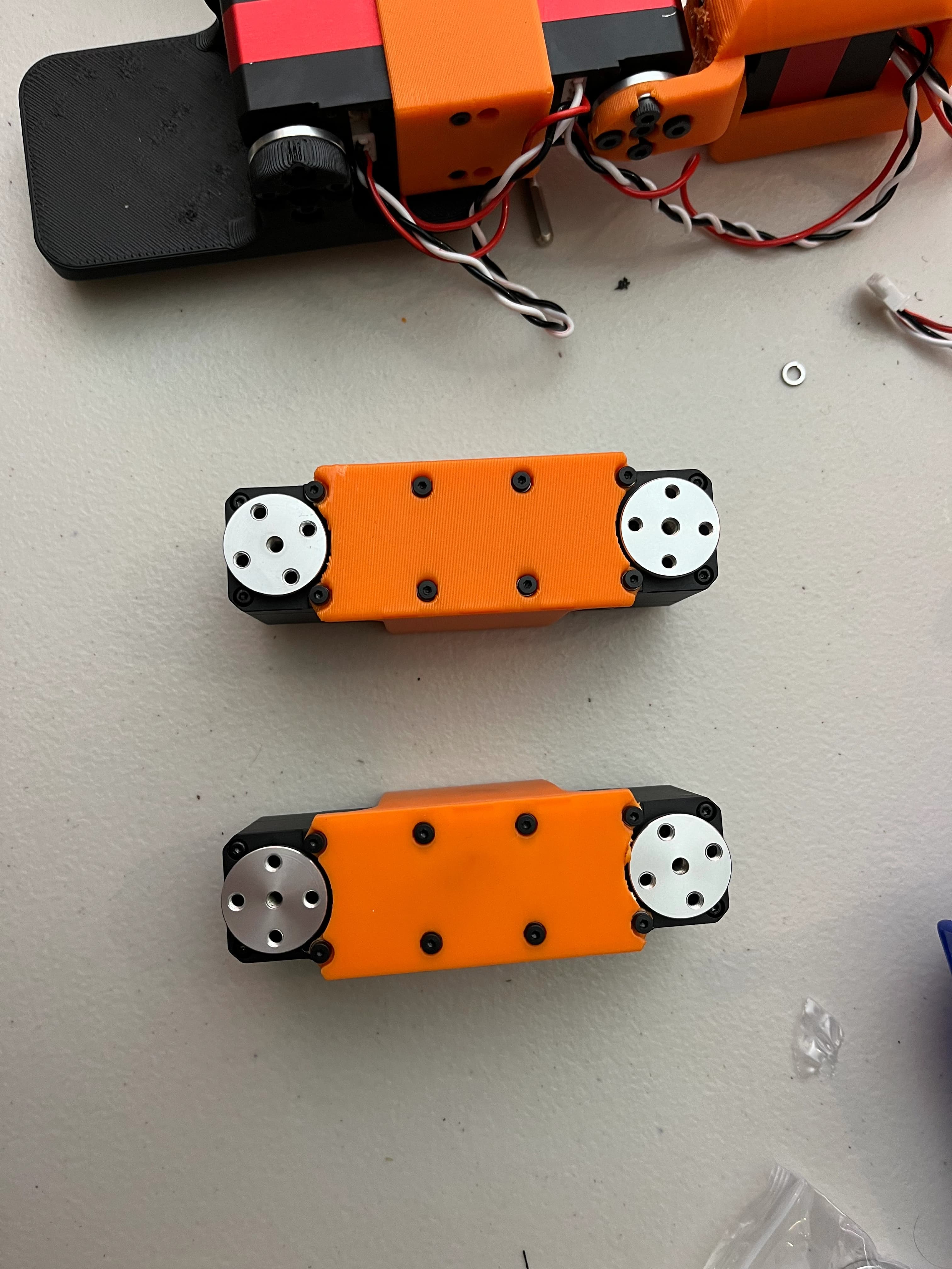
Assemble Arms
- Screw together the shoulder yaw and elbow yaw servos for both arms.
- The assembled arms should look like the image below.
Attach Shoulder Yaw Servos to Shoulders
- Connect the shoulder yaw servos to the shoulders.
Connect Wiring for Shoulder Servos
- Connect long wires to the body-side port on the shoulder yaw servos.
- Thread the wires through the holes towards the head.


Connect Elbow Yaw Servos
- Connect shorter wires from the unused port on the shoulder yaw servo to the corresponding port on the elbow yaw servo.
Attach Hands
- Attach the hands to the ends of the arms.
Final Assembly
- Your robot should now look like the image below.
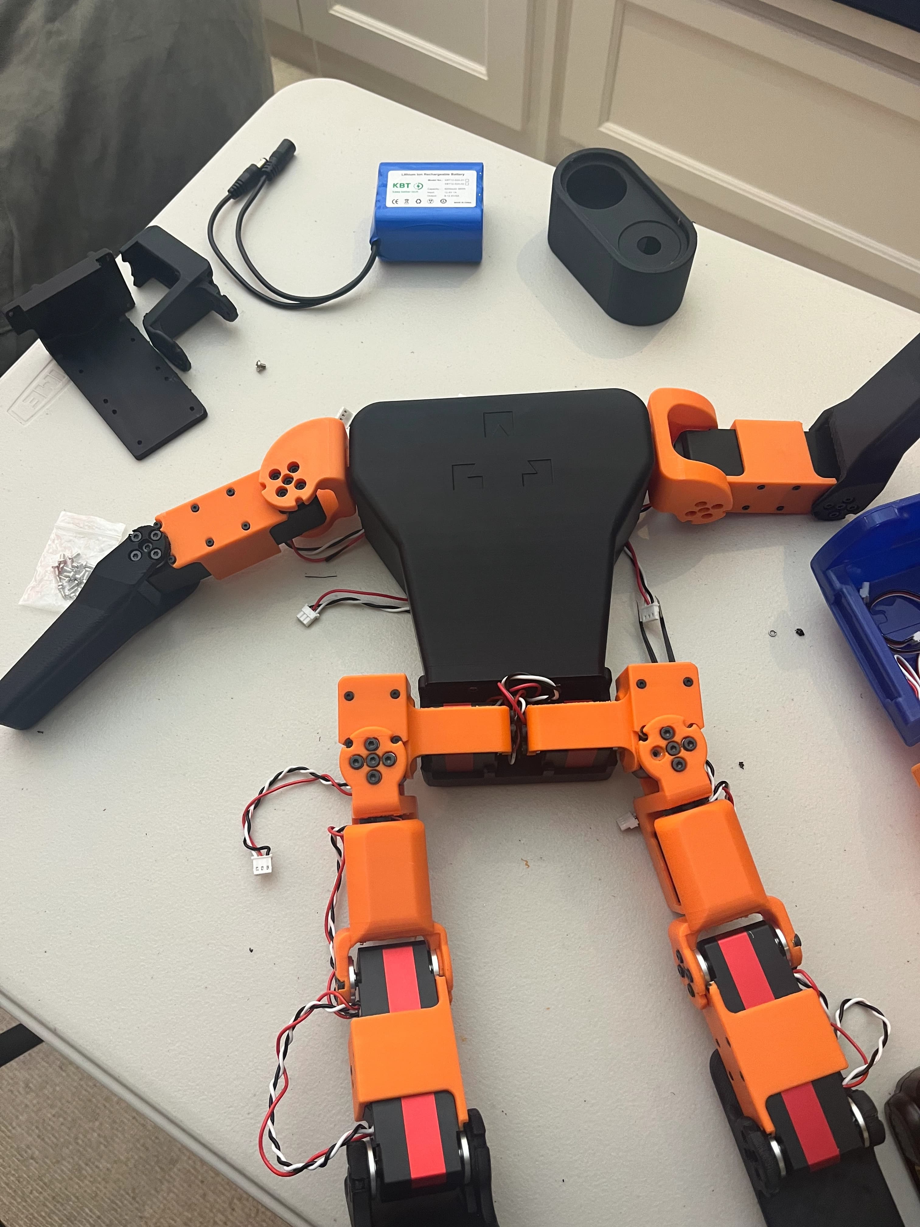
This completes the assembly of the robot. Ensure all connections are secure, and all screws are tightened with spring washers in place.
Next Steps
Once assembly is complete, it’s time to set up the OpenLCH humanoid robot platform and connect to your Zeroth-01 bot for the first time.